
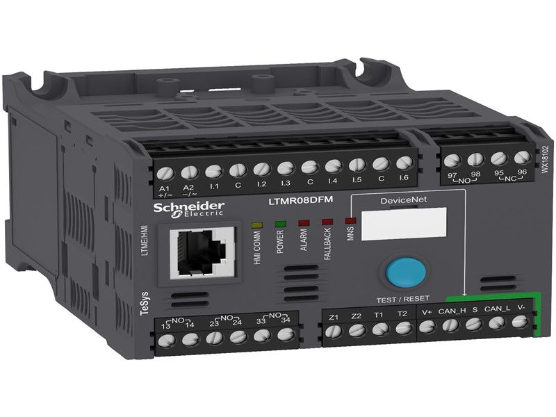
Schneider LTMR08DFM Motor controller LTMR TeSys T - 100..240 V AC 8 A for DeviceNet New & Original with very competitive price and One year Warranty
New & Original
LTMR08DFM
Please contact us for more information.
- Product description
- Contact us
Schneider LTMR08DFM Motor controller LTMR TeSys T - 100..240 V AC 8 A for DeviceNet
New & Original with very competitive price and One year Warranty
TeSys T is a smart motor management system. When associated with a short circuit protection device and a contactor,
the device provides full motor monitoring, control and protection for electrical motors.
| range | TeSys | |
|---|---|---|
| product name | TeSys T | |
| device short name | LTMR | |
| product or component type | Motor controller | |
| device application | Equipment monitoring and control | |
| measurement current | 0.4…8 A | |
| [Us] rated supply voltage | 100...240 V AC 50/60 Hz | |
| current consumption | 8...62.8 mA | |
| supply voltage limits | 93.5…264 V AC | |
| communication port protocol | DeviceNet | |
| bus type | DeviceNet ISO 1198 interface, addressing 1...64, transmission rate 125...500 kbit/s, terminal block with 4 twisted shielded pairs cable |
| [Ui] rated insulation voltage | 690 V conforming to EN/IEC 60947-1 690 V conforming to CSA C22.2 No 14 690 V conforming to UL 508 | |
|---|---|---|
| [Uimp] rated impulse withstand voltage | 4 kV supply, inputs and outputs conforming to EN/IEC 60947-4-1 6 kV current or voltage measurement circuit conforming to EN/IEC 60947-4-1 0.8 kV communication circuit conforming to EN/IEC 60947-4-1 | |
| short-circuit withstand | 100 kA conforming to EN/IEC 60947-4-1 | |
| associated fuse rating | 4 A gG for output 0.5 A gG for control circuit | |
| protection type | Thermal overload protection Phase failure Overload Load fluctuation Power factor variation Overload (long time) Earth-leakage protection Reverse polarity protection Thermal protection Phase unbalance Locked rotor | |
| network and machine diagnosis type | Running hours counter/operating time Starting current and time Fault recording Trip history information Trip context information Phase fault and earth fault trip counters Motor control command recording Event recording Waiting time after overload tripping Remaining operating time before overload tripping | |
| logic input number | 6 | |
| input current | 3.1 mA at 100 V 7.5 mA at 240 V | |
| current state 0 guaranteed | Logic input: 0...40 V and <= 15 mA for 25 ms | |
| current state 1 guaranteed | Logic input: 79...264 V and >= 2 mA for 25 ms | |
| maximum output switching frequency | 2 Hz | |
| load current | 5 A at 250 V AC for logic output 5 A at 30 V DC for logic output | |
| permissible power | 480 VA (AC-15), Ie = 2 A, 500000 cycles (output) 30 W (DC-13), Ie = 1.25 A, 500000 cycles (output) | |
| maximum operating rate | 1800 cyc/h | |
| contacts type and composition | 1 NO + 1 NC fault signal 3 NO | |
| metering type | Imbalance current Earth-fault current Average current Iavg Temperature Phase current I1, I2, I3 RMS | |
| measurement accuracy | 5...15 % earth fault current internal measurement (for current > 0.1 A) 1 % voltage (100...830 V) 3 % power factor (cos φ > 0.6) 5 % earth fault current external measurement (< 5 % or 0.01 A) +/- 30 min/year internal clock 0,02 temperature 1 % current 5 % active and reactive power | |
| overvoltage category | III | |
| connection pitch | 5.08 mm | |
| connections - terminals | Control circuit: connector 1 cable(s) 0.25…2.5 mm² (AWG 24...AWG 14) flexible with cable end Control circuit: connector 1 cable(s) 0.2…2.5 mm² (AWG 24...AWG 14) flexible without cable end Control circuit: connector 1 cable(s) 0.25…2.5 mm² (AWG 24...AWG 14) flexible without cable end Control circuit: connector 1 cable(s) 0.2…2.5 mm² (AWG 24...AWG 14) solid without cable end Control circuit: connector 2 cable(s) 0.2…1 mm² (AWG 24...AWG 14) flexible with cable end Control circuit: connector 2 cable(s) 0.2…1.5 mm² (AWG 24...AWG 14) flexible without cable end Control circuit: connector 2 cable(s) 0.5…1.5 mm² (AWG 24...AWG 14) flexible without cable end Control circuit: connector 2 cable(s) 0.2…1 mm² (AWG 24...AWG 14) solid without cable end | |
| tightening torque | Control circuit: 0.5…0.6 N.m flat screwdriver 3 mm | |
| pollution degree | 3 | |
| electromagnetic compatibility | Electrostatic discharge, 3, 8 kV air, 6 kV contact, conforming to EN/IEC 61000-4-2 Radiated RF fields, 3, 10 V/m, conforming to EN/IEC 61000-4-3 Fast transients immunity test (other circuits), level 3, 2 kV, conforming to EN/IEC 61000-4-4 Fast transients immunity test (on supply and relay outputs), level 4, 4 kV, conforming to EN/IEC 61000-4-4 Voltage dips and interruptions immunity test, 70 %, 500 ms, conforming to EN/IEC 61000-4-11 Conducted RF disturbances, 10 V, conforming to EN/IEC 61000-4-6 Temperature sensor: surges (serial mode), 0.5 kV, conforming to EN/IEC 61000-4-5 Temperature sensor: surges (common mode), 1 kV, conforming to EN/IEC 61000-4-5 Control circuit: surges (serial mode), 1 kV, conforming to EN/IEC 61000-4-5 Communication: surges (common mode), 2 kV, conforming to EN/IEC 61000-4-5 Relay outputs and supply: surges (serial mode), 2 kV, conforming to EN/IEC 61000-4-5 Relay outputs and supply: surges (common mode), 4 kV, conforming to EN/IEC 61000-4-5 Control circuit: surges (common mode), 2 kV, conforming to EN/IEC 61000-4-5 | |
| width | 91 mm | |
| height | 61 mm | |
| depth | 122.5 mm | |
| net weight | 0.53 kg | |
| web services | Web server | |
| compatibility code | LTMR |
| standards | UL 508 IACS E10 CSA C22.2 No 14 IEC 60947-4-1 EN 60947-4-1 | |
|---|---|---|
| product certifications | KERI LROS (Lloyds register of shipping) CSA ATEX UL DNV C-Tick RMRoS CCC RINA ABS EAC GL NOM BV | |
| protective treatment | 12 x 24 hour cycles conforming to EN/IEC 60068-2-30 48 h conforming to EN/IEC 60070-2-11 TH conforming to EN/IEC 60068 | |
| fire resistance | 650 °C conforming to EN/IEC 60695-2-12 960 °C conforming to UL 94 | |
| ambient air temperature for operation | -20…60 °C | |
| ambient air temperature for storage | -40…80 °C | |
| operating altitude | <= 2000 m without derating | |
| mechanical robustness | Vibrations mounted on symmetrical rail: 1 Gn, 5...300 Hz conforming to EN/IEC 60068-2-6 Vibrations plate mounted: 4 Gn, 5...300 Hz conforming to EN/IEC 60068-2-6 Shocks half sine wave acceleration: 15 Gn for 11 ms conforming to EN/IEC 60068-2-27 | |
| IP degree of protection | IP20 |

Related Products
-

Brand New SCHNEIDER analog isolated high level output module BMEAHO0412 Original In Stock
LTMR08DFM Read more -
Brand New SCHNEIDER analog isolated high level input module BMEAHI0812 Original In Stock
LTMR08DFM Read more -

Ready To Ship Original Schneider ATV930D55N4C Variable speed drive, Altivar Process ATV900, ATV930, 55 kW, 400/480 V, w/o braking unit, IP21
LTMR08DFM Read more -

In Stock Original Schneider VW3A3627 Profinet communication module
LTMR08DFM Read more